


Are You At A Loss When Trying To Understand Return Loss?
By Tom Carpenter On 05/12/2020
Voltage Standing Wave Ratio (VSWR) is taught lightly in our CWNA course and the course hints at return loss, but some students have faced challenges in grasping the concepts. The problem stems from the fact that a significant amount of physics and mathematics supports the concepts and we do not teach that level of detail. In this article, I will explain the concepts for you, in a five- to ten-minute read, that should allow you to gain some control over your thinking about return loss.
As taught in our CWNA course, VSWR is typically represented as a ratio of some number compared to 1. For example, a value of 1.4:1 or better (meaning 1.3:1 or 1.2:1, for example) is considered very good. Ratios from 1.5:1 to 1.9:1 may be acceptable, but ratios of 2.0:1 and higher are genrally thought to be from bad to very bad.
VSWR (sometimes shortened to SWR in ham radio and other RF use cases) worsens with impedance mismatches and while many components may have specification sheets that say they are 50 ohms, which is a common impedance rating for Wi-Fi gear and many other wireless systems, actual measurements can show that they are 48.8 ohms or 50.3 ohms or some other variation. The result is that you never have truly perfect match in the components and some level of VSWR will result. No systems, using cables and connectors to connect an antenna to a radio, will have a VSWR of perfection 1.0:1. We are, after all, humans engineering these things. Therefore, the explanations that refer to a VSWR of 1.0:1 as "ideal" should be understood in the same way as an isotropic radiating antenna - theoretical - for the most part.
Before I get into more on VSWR and specifically explaining return loss, I want to spend a moment explaining why poor VSWR and therefore poor return loss values matter. As an example, in one test with LoRaWAN connectivity, an antenna with poor VSWR ratings could not even connect to the LoRaWAN network from the exact same location that two other antennas with better VSWR ratings could. This, in spite of the fact that the poor performing antenna was stated to have a higher gain value. All three antennas were omnidirectional. The antenna with poor VSWR was showing a VSWR of 5.8:1 (using a VSWR/SWR meter) while the other two antennas were rated at 1.3:1 or better. While a VSWR of 5.8:1 is rare in purchased antennas, this real case reveals the potential for problem.
So why does this happen and what does VSWR have to do with return loss? Return loss is the measurement of the reflected signal strength traveling back to the transmitter from the antenna. So you have an incident wave or forward wave, which is the one that travels from the radio transmitter to the antenna. You also have a reflected wave or reverse wave, which is the one that is reflected from the antenna (or another connectivity element) back to the radio transmitter. To be clear, reflections go back and forth in the line, but most analysis considers only the impact of the initial reflection because the back-and-forth energy is attenuated to eventual untraceability.
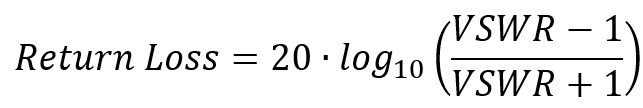
You can calculate return loss when the VSWR is known. Many antenna specification sheets list the VSWR and some list the return loss, but many do not. When the VSWR is known, the return loss can be calculated as:

Or in Excel, use the following formula:
=20*LOG10((I2-1)/(I2+1))*-1
Where I2 is the cell containing the VSWR. Note that the *-1 portion is added to the Excel formula to convert it to a positive value.
Higher return loss values are better. This statement might seem counterintuitive, so let me explain. Imagine that you are measuring the power of the reflected signal (from the antenna or another component) close to the radio transmitter. The measurement of the amplitude of the reflected signal at that point compared to the amplitude of the original transmitted signal (before reflection) gives you the return loss. Therefore, a higher return loss value indicates less reflection in the wires. With a better VSWR you also have a higher return loss. As the VSWR worsens, the return loss also decreases. This reality is why you actually want loss in this case. High return loss is a good thing. In a perfect system (no reflection), return loss is infinity as there is no reflection. Our systems, of course, are not perfect so some return loss exists. For example, with a VSWR of 1.01:1, using the above formula or equation, you can see that the return loss would be roughly 46 dB and a VSWR nearing perfection of 1.00001:1 gives a return loss of 106 dB.
Next, when the VSWR and/or return loss is known, you can also determine the percentage of reflected power. A VSWR of infinity (infinity:1) would have 100% of the power reflected back. A VSWR of 1.0:1 would have 0% of the power reflected back. With all VSWR values between infinity and 1, some percentage between 0 and 100 is reflected. To calculate the percentage of reflected power when the VSWR is known, use the following Excel formula:
=(((I2-1)/(I2+1))^2)
Where I2 is the cell containing the VSWR value. You are first calculating VSWR-1 and then VSWR+1 and then dividing the former by the latter. Finnaly, you raise the results to the power of 2 to determine the percentage of the power reflected.
Now, returning to our example of 900 MHz antennas used with LoRaWAN, the VSWR of 5.8 results in a reflection percentage of nearly 50% (49.8269896193772% to be exact). This means that, if my radio transmitter is transmitting at 100 mW, as an example, my real power passing through the antenna is only 50% of that or 50 mW from the initial forward wave (not factoring in cable losses and other phenomena occuring in the antenna beyond the scope of this article). Next, the 50% that is reflected will re-reflect at the initial insertion point from the radio transmitter and travel back to the antenna where 50% of the 50% will be reflected back again and this process will continue until the power is fully attenuated to zero. Now you can start to see why this antenna was unable to connect. Given the same output power from the radio transmitter for the other two antennas, the gain of the poor performing antenna was not enough for the communications to effectively reach the gateway.
To be fair, depending on the length of the cable and other factors, some of the energy will reflect from the radio transmitter back to the antenna and increase the radiated power as I've indicated, but let's leave that complexity alone for today as to further analysis of it. In most cases, significantly poor VSWR, such at the 5.8:1 referenced here, must exist before it will introduce significant radiated power differences. Typically losses are on the scale of less than 2 dB with more typical VSWR ratings. However, if you are purchasing cheap components or using an antenna engineered for a completely different frequency range than your use case, you can notice significant problems such as those reported here.
Have you heard of OPM (other people's money). It's a great way to live! It also applies here with a slight tweak: OPE - other people's engineering. The good news is that for systems with integrated antennas (such as Wi-Fi access points, tablets, mobile phones, and many IoT devices) OPE gives you an acceptable or even well-performing system. However, in this age of self-engineered IoT solutions or when building Wi-Fi bridge links, this knowledge plays an important role in your design/engineering decisions.
Pay close attention to VSWR and return loss values as they significantly impact the connectivity of your wireless solutions when they have significantly poor values. Thankfully, unlike broadcast radio stations, we don't have to worry as much about melting things down due to the low powers at which we transmit; however, we do have to be concerned about providing a stable link. Use the shortest cable run possible and use low VSWR-rated components and you should be able to achieve a quality link given the appropriate range and frequency use.
Tagged with: VSWR, return loss, loss percentage
Blog Disclaimer: The opinions expressed within these blog posts are solely the author’s and do not reflect the opinions and beliefs of the Certitrek, CWNP or its affiliates.