


QAM: The Basics and Beyond | Guest Blog
By Anthony M. Bruno On 04/10/2023
QAM (pronounced "kwom") stands for Quadrature Amplitude Modulation. It is a way of modulating, or changing a waveform, called a carrier wave, to encode the 1's and 0's that make up the data you wish to transmit across the RF (Radio Frequency) medium.
This is done by manipulating the phase and amplitude of the carrier wave. The number of possible phase/amplitude combinations is dependent upon the type of QAM being used (e.g., 4-QAM, 16-QAM, etc.). These phase/amplitude combinations are called symbols. Each symbol is transmitted at some fixed interval, or symbol period, to communicate one or more bits of data.
QAM does this by taking two sinusoid waves of the same frequency in quadrature and adding them together.
What does that mean?
A sinusoid is simply a smooth, continuous wave—like the cosine and sine waves you may have learned about in Math class. In fact, cosine and sine waves are two sinusoids that are 90 degrees out of phase with each other. One full cycle of a wave is considered to be 360°, so cosine and sine waves are basically two waveforms with the same frequency but offset by a quarter of their wavelength (i.e. 90°).
If you were to draw a cosine wave and a sine wave, you would draw the same basic shape for each, but they would each appear to have different origins or starting points. For example, in Figure 1 below, you'll see a green curve and a red curve. Originating at 0°, the green curve appears to be a cosine wave, and the red curve—is a sine wave. However, if you look at the red curve as originating at 90°, you will see that it now resembles a cosine wave.
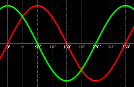
Figure 1 - Sine and Cosine waves
Why Am I Telling You This?
When two waves are 90 degrees out of phase, we say they are in quadrature. We could also say that these two waves are orthogonal to each other, which could also refer to the 90° offset, but orthogonality also implies that these two waves are discrete, unrelated, independent components that will not interfere with one another, i.e., changing one does not affect the other. When these two signals are eventually summed and transmitted, this property of orthogonality is what allows the receiver to isolate and recover the individual component waves from the combined signal.
In QAM, we usually refer to one of these waves as the I, or In-Phase component, and the other as the Q, or Quadrature component. By convention, the I component will be a cosine wave and the Q component will be a sine wave.
Now, when we take I and Q signals of the same amplitude, and add them together, the resultant wave will have a phase directly between the phases of the I and Q signals. You can see this in Figure 2 below, where we are adding the I and Q waves together. You can see the resultant wave in blue with a phase of 45 degrees—exactly between 0° (the I signal) and 90° (the Q signal).
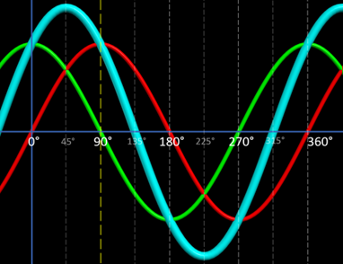
Figure 2 - Summed Cosine and Sine waves, and the resultant wave
Before we go on, I would like to say a few words about "phase." The phase of a wave indicates the location of some specific point in the wave cycle. It is expressed as an angle, usually in degrees (but, you could also use radians). For our purposes, when we mention "phase," we usually don't mean the absolute phase just described, but the phase difference between similar points on two waves.
Accordingly, when we speak of a wave having a certain phase, it's almost always in reference to another wave. So, in the above image, the blue resultant wave has a phase of 45° in reference to the In-Phase wave, or I component. Note how the I component is a cosine wave originating at 0°, and the resultant wave appears to be a cosine wave originating at 45°.
It may be confusing that we call the I component, "In-Phase." In-Phase to what? Well, it has to be called something, but really, think of it more as the reference point for the Quadrature (Q) wave.
We can invert (shift by 180°) either, or both, of these waves while still maintaining orthogonality. This gives us four distinct I/Q combinations. For example, if we invert the I signal without changing the Q signal, we get a resultant wave with a phase of 135° (see Figure 3 below). If we invert both signals, we get a resultant wave at 225°, and if we only invert the Q component, we get a resultant wave at 315°.
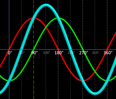
Figure 3 - Inverted In-Phase component and the resultant wave at 135 degrees
As long as the amplitudes of the I and Q waves are the same (can you sense the foreshadowing?), these are the four possible I/Q combinations and resultant phase shifts (45°, 135°, 225°, and 315°). These four symbols serve as the basis for 4-QAM (which is effectively the same as the QPSK modulation method used in 802.11).
The number preceding "-QAM" refers to the number of possible symbols used in said version of QAM. So, with 4-QAM, there are four possible symbols. To determine the number of bits that can be mapped to each symbol, you can use the following formula, where M is the number of possible symbols:
bits per symbol = log2 M
Don't be intimidated. This formula is just asking, "What power of 2 can I use to get M?" We use 2 as a base because we are using binary numbers, and each bit can only hold one of two values (0 or 1).
So, with 4-QAM, this formula would become:
2 = log2 4
We know that 22 equals 4, so each symbol in 4-QAM can be mapped to 2 bits.
Encoding More Bits Per Symbol
We can see that having only four symbols limits us to being able to encode 2 bits per symbol. Since we are always looking for ways to encode more and more bits per symbol, what can we do to create additional symbols?
Well, we can do this by varying the amplitudes of the I and Q carriers.
To better illustrate this, let's compare the constellation diagrams for QPSK and 16-QAM, both taken from Figure 17-10 in the IEEE 802.11-2020 standard. As previously mentioned, QPSK—as implemented in 802.11—is essentially 4-QAM.
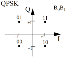
Figure 17-10 from the IEEE 802.11-2020 standard, p.2823
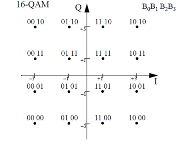
Figure 17-10 from the IEEE 802.11-2020 standard, p.2823
A constellation diagram displays the symbol set for a given modulation type. The symbols are presented as dots, or constellation points, whose positions are plotted on the diagram based on particular amplitude values of the I and Q components. The amplitudes of each component wave, or carrier, are depicted as either positive or negative numbers along the horizontal and vertical axes. The horizontal axis represents the I carrier, and the vertical axis represents the Q carrier. Negative amplitude values indicate that the wave is inverted.
The angle, or phase, of each constellation point is measured counterclockwise from the horizontal axis.
The amplitude of each symbol is measured as the distance from the constellation point to the origin of the chart where the two axes intersect.
By examining the constellation diagrams above, we can see that—as opposed to the I and Q carriers in QPSK, which are each only capable of one of two amplitude values ( 1 or +1)—16-QAM's I and Q carriers can each have one of four amplitude values ( 3, 1, +1, or +3). This gives us 16 unique phase/amplitude combinations, allowing us to encode 4 bits per symbol.
4 = log2 16
Using 16-QAM as an example, let's see how QAM works in action.
How It Works
Before we begin, did you notice the "B0B1B2B3" in the top right-hand corner of the 16-QAM constellation diagram? This tells us how the displayed symbols are formatted. For example, if we look at the symbol "1010," B0 will be "1," B1 will be "0," B2 will be "1," and B3 will be "0."
16-QAM can encode four bits per symbol. So, as new bits arrive to be modulated and transmitted, the input data stream is first divided into groups of four bits. These bits are numbered in the order they arrive, so the first bit is B0, the second bit is B1, the third is B2, and the fourth bit is B3.
These bits are sent through a serial-to-parallel converter, which splits these four bits into two groups of two bits—B0B1 and B2B3—that can be processed simultaneously.
These two-bit groups will then be mapped to one of the constellation points using the following 16-QAM encoding table from Figure 17-14 in the IEEE 802.11-2020 standard, where B0B1 will dictate the value of the I component, and B2B3 will dictate the value of the Q component.
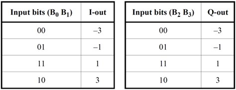
Figure 17-14 from the IEEE 802.11-2020 standard, p.2825
Each two-bit group is communicated as a pulse, the amplitude—or peak voltage—of which is determined by the table above. Here, we can see that a voltage of -3 will designate a bit value of 00, a voltage of -1 will designate a bit value of 01, etc.*
*Actual voltage levels may differ in practice, depending on the implementation.
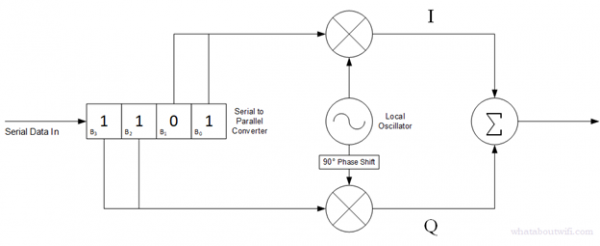
These low-frequency pulses, or baseband signals, modulate higher-frequency carrier signals generated by a Local Oscillator (LO) to create the I and Q components. Here's how this is done:
- The LO produces a high-frequency cosine signal (i.e., the carrier wave) that is multiplied by, or mixed with, the low-frequency baseband signal of B0B1. If the baseband signal carries a negative voltage, the carrier will invert, or shift in phase 180°. The resulting pulse amplitude modulated signal is the In-Phase, or I component.
- A 90° phase shift is applied to the LO signal, creating the sine carrier. This is multiplied by the B2B3 baseband signal, resulting in the Quadrature, or Q component. Again, if the baseband signal carries a negative voltage, the carrier will invert.
The I and the Q carriers are then summed together to form the 16-QAM symbol.
To visualize the entire process at a high level, here is a basic block diagram of the operation:
Beyond 16-QAM
As previously mentioned, we're always looking to cram more and more bits into each symbol. With each wireless standard, new modulation schemes are introduced—64-QAM, 256-QAM, 1024-QAM, 4096-QAM, etc., and work much in the same way as the process outlined above. The obvious differences lie in the number of bits being encoded. This means higher data rates, which is great, but there is a downside.
For example, below is Figure 21-24 from the IEEE 802.11-2020 standard which shows only the first quadrant of the 256-QAM constellation diagram.
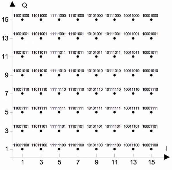
Figure 21-24 from the IEEE 802.11-2020 standard, p.3079
As you can see, the I and Q carriers in 256-QAM are each capable of sixteen possible amplitude levels ( 15, 13, 11, ... 1, +1, ... +11, +13, +15). That's a far cry from the four found in 16-QAM. All of those extra amplitude values are needed to create the 256 phase/amplitude variations. While this makes it possible to encode 8 bits per symbol, the acceptable error vector magnitude (EVM) is significantly smaller, as the constellation points are much closer together.
Error Vector Magnitude (EVM) is a measure of the accuracy of a transmitter and receiver. The EVM, in a nutshell, is how far the phase/amplitude of a received symbol deviates from the ideal phase/amplitude of the constellation point.
This means that, for the higher-order modulations, there's a much greater chance of the receiver not being able to accurately demodulate the symbol. In order to experience these high data rates, the signal to noise ratio (SNR) of the received signal needs to be very high. This means a clean RF environment with little to no interference and also usually entails being pretty close to the transmitter, i.e., being in the same room as the Access Point.
Everything comes at a cost.
If you'd like to read more about this and similar topics, visit my blog at https://whataboutwifi.com/
Wave images created with EMANIM:
Szilágyi, András (2019): "EMANIM: Interactive visualization of electromagnetic waves". Web application available at URL https://emanim.szialab.org
Blog Disclaimer: The opinions expressed within these blog posts are solely the author’s and do not reflect the opinions and beliefs of the Certitrek, CWNP or its affiliates.