


RF Myths - Part 2
By Daniel Koczwara, CWNE #217 On 09/18/2025
This is Part 2 of our series on RF myths. If you missed Part 1, you can read it here.
A few myths that seem to permeate the WLAN world. Caution, this may be controversial!
Myth #6 – More antenna gain is better.
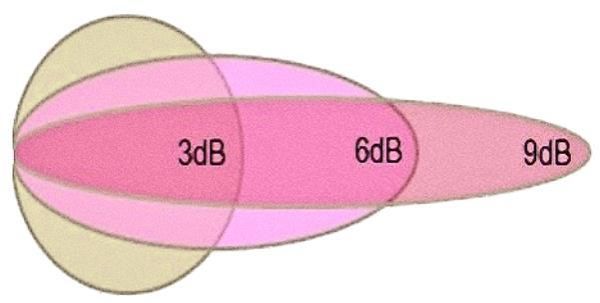
False. Gain comes from reshaping the signal to favor one area while taking away signal from others with the sum of power of all the directions in total staying the same. The greater the gain, the greater the imbalance and the more gain you have, the more potential places there are for dead zones. So no, gain is not always better. In fact, in many cases, less gain is preferred (see fig.1)
To emphasize the point, let's rephrase: "In many cases, less gain is preferred".
- In many cases, less directionality is preferred.
- In many cases, a more uniform signal in all directions is preferred.
- In many cases, having fewer dead zones is preferred.
- In many cases, signal not going much further beyond the desired coverage area is preferred.
- In many cases, more equal distribution along the horizontal and vertical planes is preferred.
A low gain dipole antenna can yield better performance where both horizontal and vertical coverage are required. For most indoor wireless networks, this is typically the case.
Myth #7 – Higher frequencies are worse for RF exposure
False. I believe this misunderstanding comes from ionizing vs. non-ionizing radiation and if you go high enough in frequency, that is, in the X-ray and Gamma-ray frequency range, it does become ionizing and extremely dangerous. This is where your electrons are literally stripped off your atoms! But radio waves (3kHz-300GHz) are much lower in frequency and therefore so much lower in energy that it isn't even close to enough energy to do anything like that. Thus, radio waves are grouped as non-ionizing type radiation.
So, we know radio waves are non-ionizing (thank goodness) but there is still the S.A.R. (specific absorption rate) (the heating effect) to worry about. If you are around very high power and/or are in very close proximity to transmitters, this can be an issue - but the worst frequency is not what you'd expect. The worst frequencies for humans are actually between 30-300MHz!
Here is a paragraph from an FCC document covering RF safety:
The quantity used to measure the rate at which RF energy is actually absorbed in a body is called the "Specific Absorption Rate" or "SAR." It is usually expressed in units of watts per kilogram (W/kg) or milliwatts per gram (mW/g). In the case of exposure of the whole body, a standing ungrounded human adult absorbs RF energy at a maximum rate when the frequency of the RF radiation is in the range of about 70 MHz. This means that the "whole-body" SAR is at a maximum under these conditions. Because of this "resonance" phenomenon and consideration of children and grounded adults, RF safety standards are generally most restrictive in the frequency range of about 30 to 300 MHz.
Source: https://www.fcc.gov/engineering-technology/electromagnetic-compatibility-division/radio-frequency-safety/faq/rf-safety
Myth #8 – Increasing power by 6dB will double distance.
False. This is only true in open space and with no obstructions. Most Wi-Fi networks are not in open space and with no obstructions. If you consider FSPL + additional attenuation from walls and objects, then to get a 2x distance, it is typically 10-12dB or more.
Example: Increase distance indoors from 10 meters to 20 meters (a 2x distance). Indoors this additional distance typically means going through at least one or two more walls and even more other possible obstructions. And just like FSPL is lower at lower frequencies, so is obstruction attenuation. This means the FSPL + obstruction attenuation is even greater at higher frequencies. The result is 5 and 6GHz frequencies will have an even greater amount of total attenuation than 2.4GHz. Keep this very important aspect in mind when designing your Wi-Fi networks! Also, don't forget RF coverage is a 3-dimensional thing.
Myth #9 – 5GHz is faster than 2.4GHz because there are more wave cycles in 5GHz.
False. If that were true, then:
- Why are both 802.11a and 802.11g speeds the same 54mbps?
- If increasing the frequency itself increased the data rate, then wouldn't channel 11 be slightly faster than channel 1 in 2.4GHz, and channel 165 slightly faster than channel 36 in 5GHz?
But there really are more "phase change opportunities" in the same amount of time with 5GHz so why isn't it faster?
The reason is because we are confusing the carrier frequency with symbol frequency. The RF carrier frequency that symbols are transmitted on is not important. It's the symbol rate per second that matters.
Along with the frequency rate of the symbols, there are a few other factors that determine overall data-rate (below).
Data rate comprises of the following variables:
- Modulation rate (symbol complexity / how many bits in each symbol) = the "QAM"
- Error correction ratio (total bits sent divided by FEC ratio) = final actual data bits
- How many symbols are sent at the same time (subcarriers / data sent in parallel)
- The rate at which symbols are sent (how many symbols per second / the frequency)
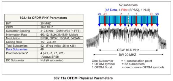
Fig.2 Courtesy: https://helpfiles.keysight.com/csg/89600B/Webhelp/Subsystems/wlan-ofdm/content/ofdm_80211-overview.htm
Let's look at 802.11a and 802.11g in more detail and what matters for Data Rate
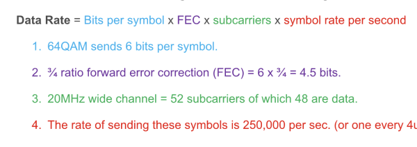
- The maximum modulation complexity of 802.11a and 802.11g is 64QAM (for 54mbps). 64QAM means 64 different phase and magnitude possibilities which is 6 bits of data. This is called a symbol (or constellation point).
- At 54mbps, there is a forward error correction (FEC) ratio of ¾ so the 6 bits of data is reduced down to 4.5 bits.
- Each one of these 64QAM 6-bit symbols will be transmitted on one subcarrier each. OFDM uses multiple subcarriers. With a 20MHz 802.11a and 802.11g signal, there are 48 data subcarriers. So, if each subcarrier carries one of these 64QAM 6-bit symbols and there are 48 subcarriers, this effectively means there are 48 6-bit symbols being transmitted in parallel. In a way, it's like having 48 separate channels and 48 separate receivers, each carrying their own 6 bit symbol of data.
- How many of these 48 symbols in parallel are sent per second? For 802.11a and 802.11g, one every 4us (3.2us + 0.8us guard interval). 4us = 250,000 per sec.
Calculating the 802.11a and 802.11g data rate
Notice that where this subcarrier is transmitted (what frequency it uses) is nowhere part of the calculation.
I'll give you that 20MHz of RF spectrum is needed due to the subcarriers, their spacing, as shown in Fig.2 but this can happen pretty much anywhere in the entire RF spectrum whether that it be between 10MHz-30MHz, 902-922MHz, 2.45-2.47GHz, or 60.02 to 60.04GHz etc.
To hit this home further, if you were to receive each subcarrier individually. Imagine all 48 subcarriers were spaced in random spots on RF spectrum. One at 10.000MHz, another at 55.000MHz, another at 905.500MHz etc. As long as they were all "collected" by the receiver, the data rate would be the same. Of course, receiving them that way wouldn't be practical but the main point is that the center transmit frequency of each of these subcarriers does not matter, instead it is the frequency of the symbols plus the three other variables mentioned (number of symbols in parallel via multiple subcarriers, the modulation complexity, and error correction overhead) and not carrier frequency itself.
Myth #10 – 60GHz cannot go through walls or is 100% purely LOS.
False. 60GHz is still RF. It still has the same fundamental characteristics as do lower frequencies. Meaning the link budget calculation still applies. It's just that the FSPL + object attenuation values are much higher. But with short distances and a high EIRP, you can still get through some pretty high attenuation material.
In fact, there is a company – Airvine, based in Irvine, CA, United States that specializes in this very thing.
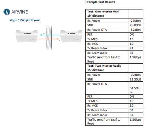
Fig.3 Courtesy: https://cousides.sirv.com/collateral/Airvine-Getting-Started-Guide-Wave-Tunnel.pdf
With one interior wall and 10 feet of distance, the high gain directional beam forming antennas work together to create a "PtP" indoor link of a very good -52dBm signal despite having to go through a wall, with plenty of SNR to support over 1gbps.
Tagged with: rf, radio frequency, 60GHz, 802.11ad, Wi-Fi, rf myths
Blog Disclaimer: The opinions expressed within these blog posts are solely the author’s and do not reflect the opinions and beliefs of the Certitrek, CWNP or its affiliates.