


RF and Wi-Fi Myths - Part 3
By Daniel Koczwara, CWNE #217 On 02/02/2026
As I continue with my next round of myths, I am expanding it beyond just RF. It will now include anything related to Wi-Fi networking. Thank you for reading and please feel free to reach out to me for inaccuracies and even disputes! The goal is to improve understanding and a reminder that we can all learn from each other.
Myth #11 – The Main Cause of Poor Performance of an AP When Too Close to Metal is From Multi-Path Interference.
False. It is commonly assumed that if an AP is improperly installed too close to metal, that the main reason for it performing poorly is due to multi-path. Although it is true multi-path will likely occur and cause a degradation of performance, something more sinister is occurring.
The bigger issue is the distortion of the radiation pattern itself. When an AP is too close to metal (in particular, less than one wavelength), coupling can occur with the metal and antenna, causing the metal to act as part of the antenna system itself. When this happens, you can basically throw the AP's Azimuth (horizontal) and Elevation (vertical) charts out the window. This close proximity from the antenna is referred to as the "near field".
Near Field vs. Far Field
The boundary between the near field and the far field isn't a sharp line, but it's typically considered to be within one wavelength (λ) of an electromagnetic source, with the far-field starting at roughly two wavelengths away (or greater) (https://en.wikipedia.org/wiki/Near_and_far_field).
Using the Yagi antenna design as an example to better explain this
Yagi antennas use near field resonating elements at calculated distances to create a directional effect. The spacing is crucial for best performance. The figure below is an example of an 5 element 440MHz antenna. The D.E (driven element) is ½ wavelength (effectively a dipole), while the reflector is slightly larger and "director" elements slightly smaller than the driven element (additional director elements become progressively smaller and smaller) at precise distances from each other. You can play around with this "Yagi calculator" using the source link below. The main takeaway that I want you to notice is how critical these precise distance values are (down to a 32nd of an inch).
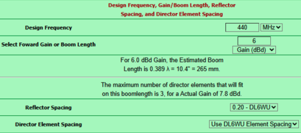
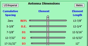
Source: https://k7mem.com/Ant_Yagi_VHF_Quick.html
Now imagine putting some random non-resonant length of metal at some random distance from these elements. It would completely ruin the design intention and performance of this antenna. The same thing would occur with a dipole antenna. A dipole in a sense is just a "one element Yagi".
Another thing worth mentioning is that when placing a Wi-Fi access point very close to metal is that it will also likely cause a very high SWR (Standing Wave Ratio). This happens for the same reason - because the metal is in the near-field of the AP's antenna. This nearby metal is not going to be resonant at the design frequency of the actual antenna (such as 2.40-2.50GHz or 5.15-5.90GHz etc.).
This detuning means that the power transfer from transmitter to antenna will no longer be efficient. A lot of the power instead of being transmitted out the antenna will instead be reflected back towards the transmitter. https://menacerc.co.uk/vswr-return-loss-vs-power-transmitted
Antennas are designed to have a specific impedance, typically 50 ohms for Wi-Fi, to match the transmitter's output and the coaxial cable connecting them. When an antenna is placed near a large metal object, the metal acts as a reflector and can alter the antenna's electrical properties. This change in properties is known as detuning and it effectively changes the antenna's impedance.
This impedance mismatch causes a portion of the transmitted signal to be reflected back down the transmission line, which directly leads to a high SWR reading. This reflected power is not only wasted but can also cause the access point's components to overheat and, in some cases, even fail over time.
In short, putting a Wi-Fi access point too close to metal fundamentally changes how its antenna functions, creating an impedance mismatch that is measured as a high SWR and skewing the intended radiation pattern. This should be the real reason why network professionals recommend mounting access points away from large metal surfaces.
Myth #12 – The Fresnel Zone Must Be Clear
False. The Fresnel zone is not an on/off switch in that if you don't have the Frensel zone clear (or at least 60% clear), you won't have a link. Or if there is a link, it will be very poor or not work well.
If this were truly the case, how would indoor Wi-Fi work at all? Think about it. Most, if not nearly all indoor 2.4,5,and 6GHz wireless networks are NLOS. Most of the time there are walls and objects between the client device and AP. In this NLOS scenario, the entire Frensel zone is fully obstructed, yet it still works. So yes, a Wi-Fi link can still work, but performance (speed, stability, range) will be degraded significantly. For very short links like indoor Wi-Fi, it mostly lives outside the Fresnel zone.
For farther PtP/PtMP links, there is a larger amount of attenuation from FSPL (free space path loss). This large loss makes these farther links unable to handle any additional attenuation (i.e. from a blocked direct path). Unlike in an indoor short range scenario, where FSPL hasn't hit as hard yet, there is still enough signal to handle the obstruction attenuation and penalty of not being in "the Fresnel Zone".
Myth #13 – 2.4GHz, 5GHz, and 6GHz Signals Are Attenuated By Rain
It's actually true! So why would I say it's a myth then?
Because the attenuation is so small, it should not be taken into any consideration for links less than typically 10km. It only even starts to become an issue at frequencies 10GHz and up combined with distances greater than 10km. Certainly, a non-issue for any on-premise outdoor Wi-Fi networking.
Here's some numbers assuming 25mm (1in.) per hour of rainfall:
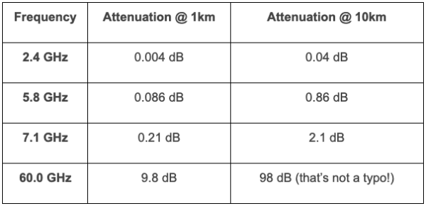
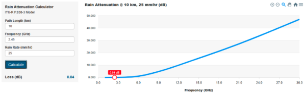
Fig.3 source: http://linklab.landseaskyspace.com/rain.html
It is generally accepted in the wireless community that rain needs to be taken into consideration for PtP links using frequencies 10GHz and up or in rare cases, very far 5GHz links. It's never a factor for an on premise 2.4GHz/5/6GHz Wi-Fi network, even if several hundred meter bridge links are in the mix. It just isn't enough to matter.
As you can see though for 60GHz, rain is a huge factor! This is why you'll see many 60GHz manufacturers provide a secondary sub-10GHz failover radio such as 5GHz (albeit at a lower throughput) but at least still up to provide service.
Myth #14 – There is Very Little Signal Outside of an Antenna's Radiation Pattern.
False. I see this commonly. We get hung up on radiation patterns with the idea that if we are just outside an antenna's radiation pattern, the signal will be terrible. An application that comes to mind is warehouse installations. There seems to be a huge emphasis on the idea that if the AP is mounted up high, it must have down-tilt or be designed specifically for this application or the signal will be RF shadowed directly below it and hardly work at all. But what is overlooked is the advantage of sheer proximity. While it is true, the closer you get to the AP, the more you will be under the radiation pattern – but you are also at the same time – GETTING CLOSER. If you are only a few feet away from the AP, directly below it, even with a huge 30dB null, you may still find yourself still with a good signal. And as you walk further away, although the FSPL is increasing, you are also working your way back into the antenna pattern.
I still recommend using an antenna for the application though! It will certainly perform better if you do! My point is that it isn't as much of a factor as it is led out to be. Many times, it will still work and additionally, if high performance is not a requirement, it can likely still work just fine.
Myth #15 – 2.4GHz Should Always Be Avoided.
False. In fact, 2.4GHz is vastly superior over 5 and 6GHz when it comes to range and signal penetration through obstructions. There is a 6 to 7dB advantage in the FSPL alone. Combining FSPL with reduced obstruction attenuation, this typically results in a 10+dB signal advantage in most indoor deployments. There are many excellent use cases for 2.4GHz. Specifically non-latency sensitive, non-bandwidth intensive devices that require longer range. Such examples are IoT devices such as a thermostat, pool controller, or a sprinkler controller. A sprinkler controller is often installed on the outside perimeter of a home, at the far end of where an access point / home router would be. And it needs just kilobits of data and is not dependent on any real time data delivery.
Tagged with: rf, radio frequency, 60GHz, 802.11ad, Wi-Fi, rf myths, WiFi myths, Wi-Fi Myths
Blog Disclaimer: The opinions expressed within these blog posts are solely the author’s and do not reflect the opinions and beliefs of the Certitrek, CWNP or its affiliates.